Configuration of the Smart Panel v6
TutorialSmart Panel in the v6 version is available for Object Manager in version 1.4.1 and higher and for CLU with firmware 5.08.01 and higher.
Configuration parameters
In the latest version of the Smart Panel v6 module, new configuration parameters have been introduced for such objects as:
PANEL,PANEL_PAGE,PANELSENSTEMP.
The full list of changes introduced in the V6 version can be found in the release notes of the given version: Release Notes - Smart Panel module
New functionality
The mechanism of informing about incorrect configuration / entering to the Distributed Logic mode
A new functionality introduced with the v6 version is the mechanism of informing the user about a wrong configuration or entering to the Distributed Logic mode. This mechanism is based on the fact that the module waits about 10 seconds for receiving the configuration after sending it or restarting the system. After this time, the waiting period for configuration ends and the user will be informed about a misconfiguration or switching to Distributed Logic mode by one short and low beep.
Distributed Logic mode
Another functionality added to the latest version of the Smart Panel module is the Distributed Logic mode. It is available from version 6.1.8-2115 and higher. Detailed information on the configuration and operation of Distributed Logic is included later in the description.
Changing the UI and the mechanism of operation of Thermostats pages
The Smart Panel module in version v6 offers a refreshed UI of Thermostats websites, as well as new functions. The method of creating and configuring a page with the use of Thermostats type objects is the same as for the previous versions - see User Manual chapter 5.9. Creating a configuration using the Thermostats page object.
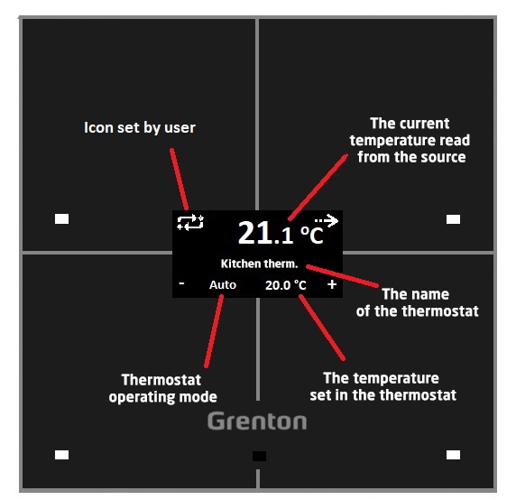
Thermostat UI change
The diagram below shows an overview the appearance of the refreshed thermostat on the Smart Panel screen. Several elements have changed:
- entering the icon in the upper left corner - by default, the "chmode" icon on the SD card is displayed (the icon is shown in the diagram). However, if this icon is not present on the SD card, the word "mode" will be displayed. Additionally, the user can enter his own icon using the
SetObject_X_CustomIconmethod or the featureObject_X_CustomIcon,
- using the arrow, the user can go to the next thermostat on the page (short press of the button in case of more than one thermostat on the page) or go to the next page (short press in case of one thermostat on the page, longer press of the button in case of more than one thermostat on the page ),
- dots have been introduced next to the arrow, which indicate the number of the currently displayed thermostat (one dot -
Object_1_Id, two dots -Object_2_Id, etc.). If there is only one thermostat on the website, the dots are not displayed,
- using "-" / "+" it is possible to change the set temperature and the operating mode of the thermostat from Auto to Manual,
- a longer pressing of the upper left button (hereinafter referred to as 'mode') turns the thermostat off / on or changing from Manual mode to Auto mode,
- when the thermostat is turned off, the set temperature disappears and the word "Off" appears, which is located centrally,
- the display of temperature read from the source has also changed - now the temperature value before the decimal point is displayed in larger font, while the value after the decimal point and the unit are displayed in a smaller font. Additionally, the display of this temperature depends on the size of the entered icon - more on this subject in the next section.
New features on the Thermostats page
From version v6 of the Smart Panel module, new functionalities are available on the Thermostats page. It is related to the changes made to the UI of the thermostat.
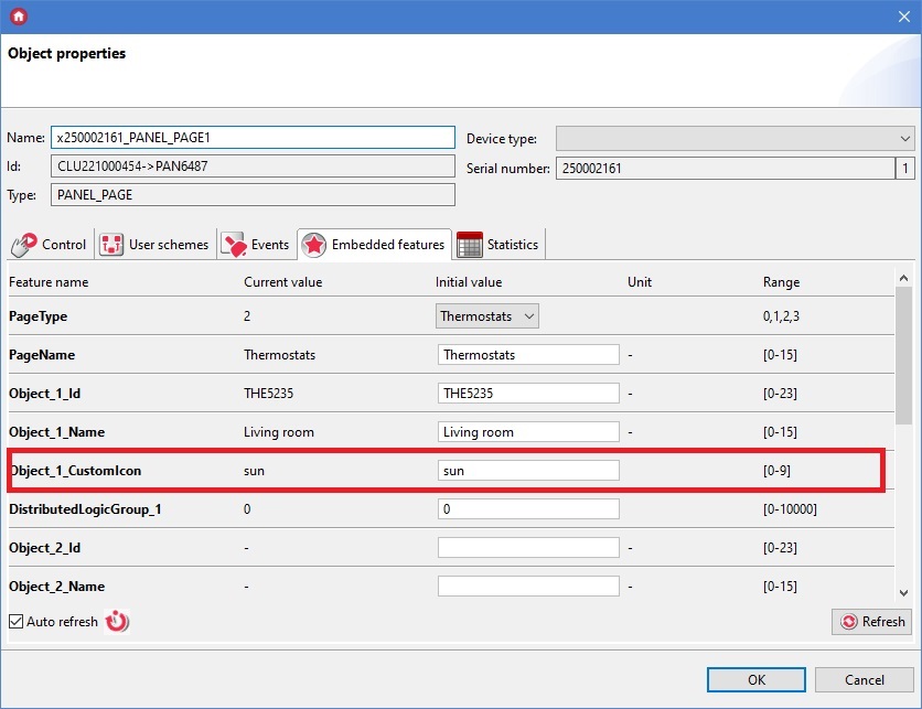
Possibility to set your own icons
The first new functionality is the aforementioned possibility for the user to set their own icons in the upper left corner of the display. Their change is possible both through the SetObject_X_CustomIcon method as well as through the feature Object_X_CustomIcon. The width of the entered icon affects the "x" coordinate of the current temperature. The 64 x 32 pixel icons are allowed. If the icon width x > 64 is exceeded, only the icon itself will be drawn on the display - the UI of the thermostat will not be displayed - it is the so-called "big icon" mode. To go back to the thermostat interface, set an icon whose width does not exceed 64 pixels.
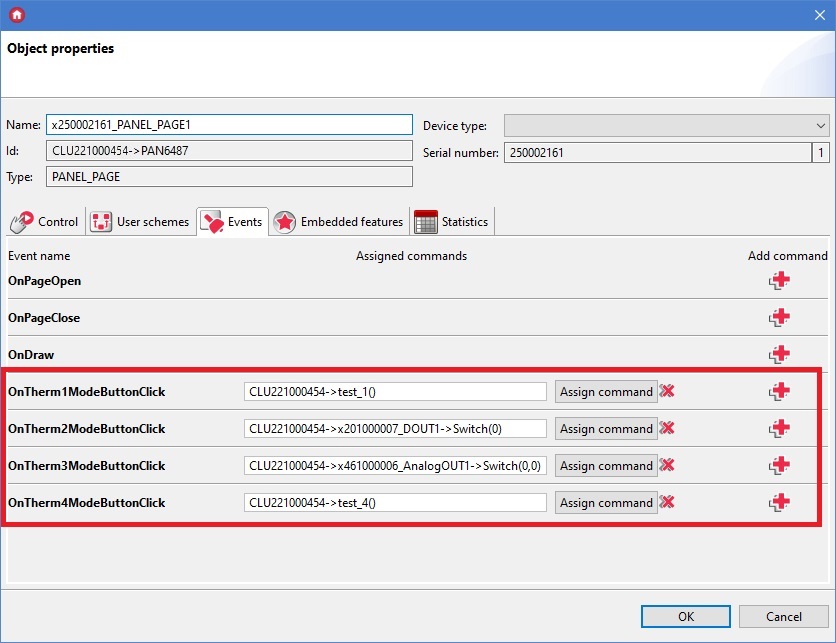
Ability to assign actions to new events
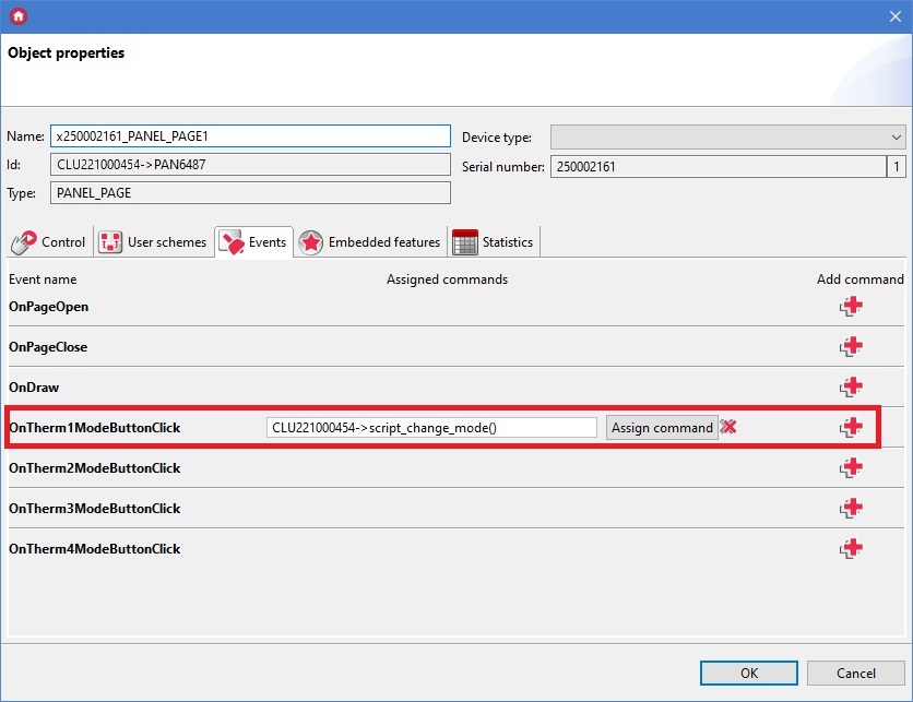
Another functionality introduced in the new version of the module is the ability to assign actions to new events OnThermXModeButtonClick, where X is the number of the thermostat on the page. This event is generated when the 'mode' button (upper left button) is clicked.
An example of configuration of new functionalities
Local thermostat configuration with operation change (heating / cooling) - the following objects are used to create this configuration:
- Thermostat virtual object,
- DOUT1 object (e.g. Relay module) - responsible for heating / cooling activation - used in the Thermostat virtual object,
- DOUT2 object (e.g. Relay module) - selection of what is to be switched on: heating or cooling - used in scripts.
The following screenshot shows the configuration of the PANEL_PAGE object and the Thermostat virtual object in the default setting, which is heating.
Configuration of the OnTherm1ModeButtonClick event:
Script script_change_mode() that changes the operating mode of the thermostat from heating to cooling and vice versa:
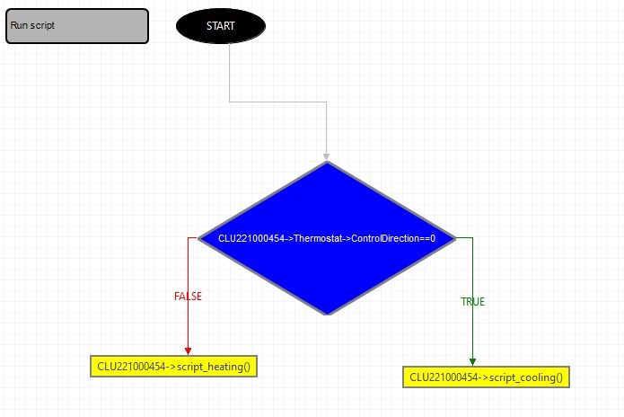
The above script in the text version:
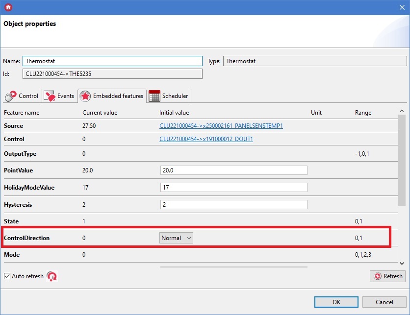
if(CLU221000454->Thermostat->ControlDirection==0) then
CLU221000454->script_cooling()
else
CLU221000454->script_heating()
end
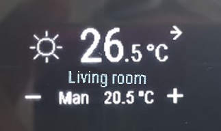
Script script_heating() for changing the ControlDirection feature to a value responsible for heating, as well as changing the icon and selecting heating / cooling:
CLU221000454->Termostat->SetControlDirection(0)
CLU221000454->x201000007_DOUT2->SwitchOff(0)
CLU221000454->x250002161_PANEL_PAGE1->SetObject_1_CustomIcon("sun")
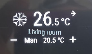
Script script_cooling() for changing the ControlDirection feature to the value responsible for cooling, as well as changing the icon and selecting heating / cooling:
CLU221000454->Termostat->SetControlDirection(1)
CLU221000454->x201000007_DOUT2->SwitchOff(1)
CLU221000454->x250002161_PANEL_PAGE1->SetObject_1_CustomIcon("cold")
Predefined button behavior
| Button | Short/long press | Description of behavior |
|---|---|---|
| Top left | Short press (click) | Generating an OnThermXModeButtonClick event, where X is the number of the thermostat on the page |
| Top left | Long press (hold) | Change of the thermostat status: Off/On. In addition, it allows to switch from Manual mode to Auto mode |
| Top right | Short press (click) | Go to the next thermostat on the page if there is more than one thermostat on the page Go to the next page if there is only one thermostat on the page |
| Top right | Long press (hold) | Go to the next page |
| Lower left | Short press (click) | Reduction of the set temperature (PointValue) by 0.1 ° C, as well as changing the operating mode from Auto to Manual |
| Lower left | Long press (hold) | Reduction of the set temperature (PointValue) - as long as the button is held down, as well as changing the operating mode from Auto to Manual |
| Lower right | Short press (click) | Increasement of the set temperature (PointValue) by 0.1 ° C, as well as changing the operating mode from Auto to Manual |
| Lower right | Long press (hold) | Increasement of the set temperature (PointValue) - as long as the button is held down, as well as changing the operating mode from Auto to Manual |
Configuration of the Distributed Logic mode
The Smart Panel module on the first connection to the bus have Logic Distributed Mode enabled - value 1 of the
DistributedLogicGroup_1 - DistributedLogicGroup_4 (Default Mode) feature - assigned to four physical buttons - the inputs can control the outputs, as described below. After performing CLU Discovery and sending the configuration, the mode turns off.Mode configuration for Smart Panel module
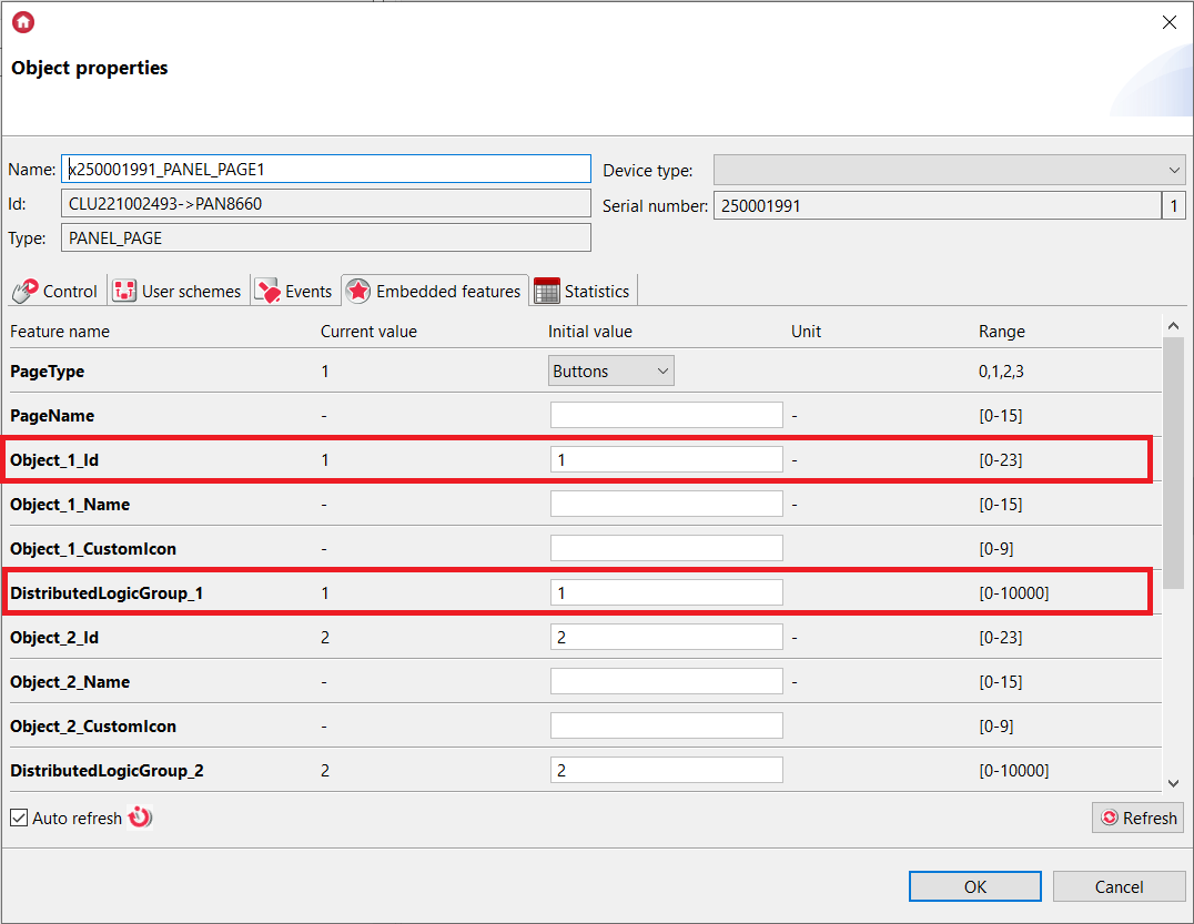
For Smart Panel module, the binding on the input takes place in the PANEL_PAGEx object. Before that, PANEL_PAGEx objects must be linked with the appropriate PANEL_BUTTONx objects by setting the appropriate values in the Object_x_Id field. If there is no connection to the CLU, in Distributed Logic mode all 16 buttons can work with the change of pages using gestures.
Distributed Logic is only possible in the
Buttons mode of the PANEL_PAGEx object.Operation of Distributed Logic between PANEL_PAGE with PANEL_BUTTON and output objects
Events and triggered actions are set statically and cannot be changed.
Available actions while running in the Distributed Logic mode:
A.PANEL_PAGE with PANEL_BUTTON object set and DOUT objects
- Press the button (SwitchOn) -> Switching on the given DOUT output.
- Release the button (SwitchOff) -> Switching off the given DOUT output.
- Short button press (Click) -> Change of state to the opposite of the given DOUT output.
B. PANEL_PAGE with PANEL_BUTTON object set and DIMM objects
- Press the button (SwitchOn) -> Switching on the given DIMM output.
- Release the button (SwitchOff) -> Switching off the given DIMM output.
- Short button press (Click) -> Change of state to the opposite of the given DIMM output.
C. PANEL_PAGE with PANEL_BUTTON object set and LEDRGBW objects
- Press the button (SwitchOn)-> Switching on the given LEDRGBW channel.
- Release the button (SwitchOff)-> Switching off the given LEDRGBW channel.
- Short button press (Click) -> Change of state to the opposite of the given RGBW LED channel.
D. PANEL_PAGE with PANEL_BUTTON object set and ROLLER_SHUTTER objects
- Press the button (SwitchOn) -> Switching on the UP or DOWN
ROLLER_SHUTTERoutput, depending on the previous direction. - Release the button (SwitchOff) -> Switching off the given connected output (UP or DOWN).
- Short button press (Click) -> Change of state to opposite
ROLLER_SHUTTER:- if the relays (UP / DOWN) are turned off - switching on the UP or DOWN relay, depending on the previous direction,
- if the UP or DOWN relay is on - the relay is turned off.
Switching the relay UP or DOWN means switching on the relay without switching off after the MaxTime time has elapsed. The relays should be turned off with a given control input of the
ROLLER_SHUTTER object in the Distributed Logic mode.Default Mode
If the value of the DistributedLogicGroup feature is set to 1 for a given object, it works in the Default Mode. This is a special operating mode set by default for each object:
The events and triggered actions are statically set and cannot be changed.
Smart Panel module - controls all output modules (RELAY 4HP DIN, RELAY 2HP DIN, DIMMER MOSFET, ROLLER SHUTTER DIN) in TFBUS network, which are also in Default Mode, for example:
- SMART PANEL
PANEL_PAGE1featureDistributedLogicGroup_1--> RELAY 4HP OUT1 | RELAY 2HPOUT1| DIMMER MOSFETDIMM1|ROLLER_SHUTTER1. - SMART PANEL
PANEL_PAGE1featureDistributedLogicGroup_2--> RELAY 4HPOUT2| RELAY 2HPOUT2|ROLLER_SHUTTER2. - SMART PANEL
PANEL_PAGE1featureDistributedLogicGroup_3--> RELAY 4HPOUT3|ROLLER_SHUTTER3. - SMART PANEL
PANEL_PAGE1featureDistributedLogicGroup_4--> RELAY 4HPOUT4.
Switching the relay UP or DOWN means switching on the relay without switching off after the MaxTime time has elapsed. The relays should be turned off with a given control input of the
ROLLER_SHUTTER object in the Distributed Logic mode.For a Smart Panel module running in the Distributed Logic Default Mode, the behavior described above is identical for any
PANEL_PAGE object (PANEL_PAGE1 - PANEL_PAGE4).